News
New Reece Bridge in Niagara Region finished ahead of schedule
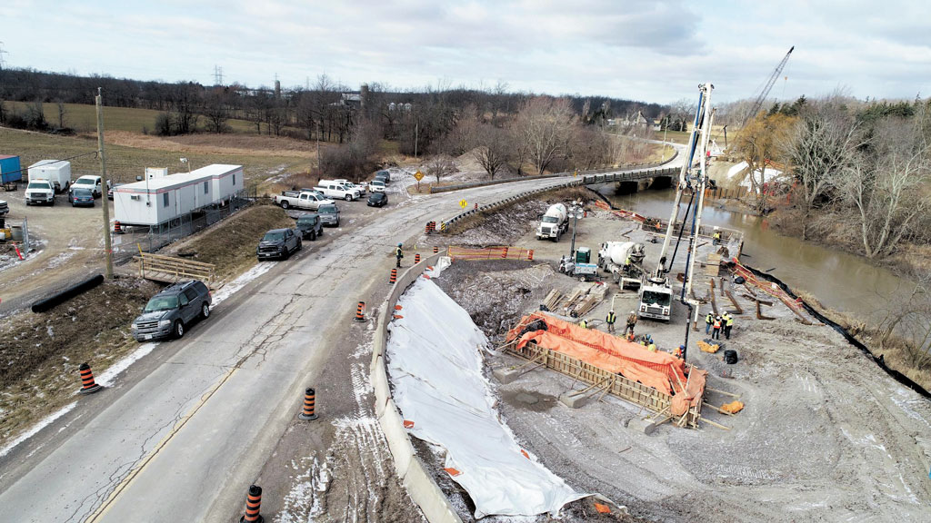
Construction of new $8.3-million two-span steel girder Regional Road # 69 Reece Bridge in Niagara Region was supposed to be wrapping up this spring — except that Rankin Construction finished the job last October.
A number of factors came into play to facilitate the early completion, says Cam Milne, senior project manager with Niagara Region’s transportation engineering division.
“The contractor was able to accelerate the construction schedule using experienced tradesmen and project management staff that fully understood the scope of the project and efficiently planned each of the tasks with excellent subcontractors.”
In addition, a project team comprised of regional officials, consultant Ellis Engineering Inc., and the contractor met on site every two weeks to review the construction progress and make on the spot decisions.
As well, Rankin and foundation contractor HC Matcon “worked aggressively” through the winter of 2018/19 to build the foundations so that construction of the superstructure could begin the following spring, he says.
Using a caisson drilling rig, the subcontractor drilled 900-mm diameter steel-lined reinforced concrete caissons into dolostone bedrock to a depth of between one to two-metres depth, he says.
Apart from the early completion, the project might be considered unique in light of the fact the project partners had to contend with complex soil conditions and that the bridge also had to be designed and erected on a different vertical and horizontal alignment than its predecessor.
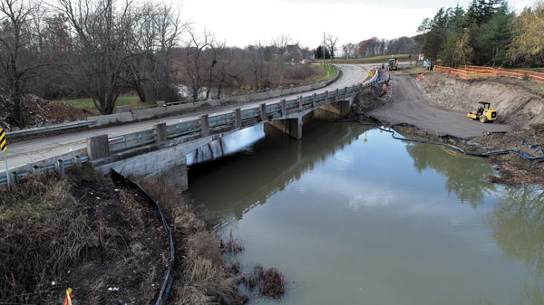
Regional Rd. 69, also known as Twenty Mile Road, is an important thoroughfare linking several communities in the Townships of West Lincoln and Pelham and for more than 70 years vehicles crossed Twenty Mill Creek on a two-span reinforced concrete bridge which the region believes was built in 1950.
As documented in a 2009 inspection, that bridge was in poor condition through a combination of severe concrete deterioration, spalling, and exposed corroded reinforcing steel on the bridge deck soffit and facia.
“The asphalt wearing surface was in poor condition and the timber railings had to be protected with temporary concrete barriers to provide adequate protection for vehicular traffic,” says Milne, noting those barriers significantly reduced the roadway width.
Three years later the Region completed an environmental assessment which recommended replacing the old bridge with a new structure slightly offset to the east. That recommendation was intended to rectify several safety hazards stemming from the road’s configuration.
There were very tight S curves at both approaches to the bridge, while at the west end there was a very steep vertical grade change and an intersection with the local Campden Sideroad. That horizontal and vertical geometry resulted in poor sight lines and increased the potential for vehicles to collide or veer off the road, he explains.
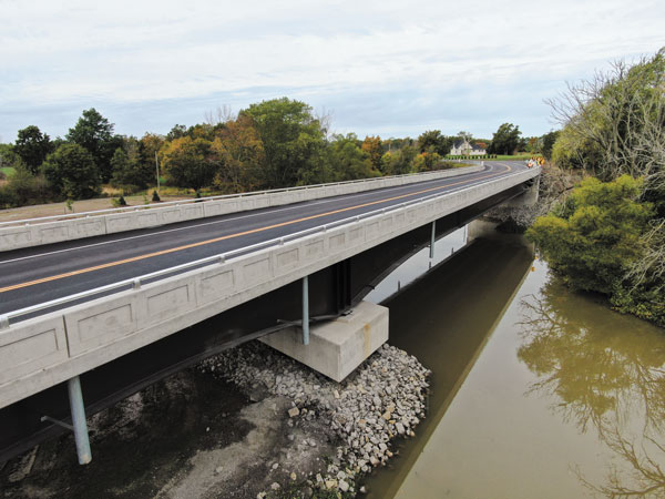
Erecting the new bridge corrected that roadside geometry and also allowed the old structure to remain open while construction was taking place, says Milne.
As well, the west end of the new bridge was built approximately two metres higher than the old one to eliminate the steep vertical grade change. Six-metre-tall RECO walls were used to construct the west approach and limit the amount of fill that was required to build up that approach.
But rectifying those geometric constraints and designing and erecting the bridge was not straightforward and required extensive consultations. At the east approach to the new site there is a large flood plain consisting of four metres of soft silty clay overlaying the dolostone bedrock.
To avoid construction in the river, Ellis Engineering had originally proposed constructing a single span bridge and placing approximately four metres of fill on the approach to accommodate the new alignment. However, geotechnical consultant Landtek Limited determined it would take approximately seven to 10 metres for the fill to consolidate.
Instead, it was decided with the Region to construct a second bridge span over the soft soils. A cost comparison had also determined that the cost of the additional span would be similar to the filling operation, he says.
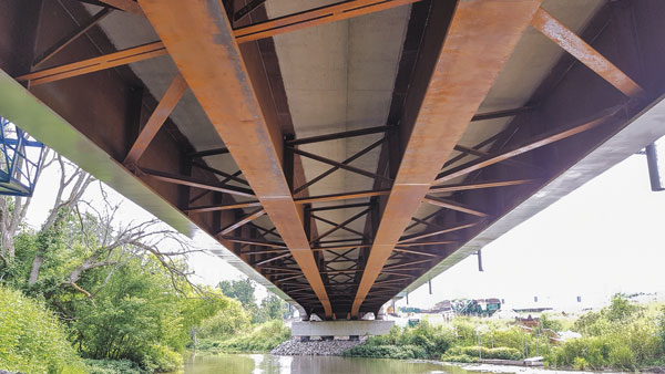
But that decision wasn’t a straightforward matter either. A number of steel compositions types were evaluated and it was determined that a bridge should consist of variable-depth steel I-girders with a composite concrete deck and a 20-degree skew. The west span would have a length of 63 metres and the east span over the flood plain would have a span of 47 metres.
However, those long spans and tall west abutment would (and are) place substantial loads on the foundations and then there was the issue of the site’s soft overburden soils, he points out.
“The design team was challenged to design foundations that were supported in both the horizontal and vertical direction by the underlying dolostone bedrock.”
Ultimately, the preferred solution chosen was the one using the 900-mm diameter steel-lined reinforced concrete caissons socketed into the rock, he says.
Touching on other aspects of the project, Milne says the bridge’s four variable depth steel I-girders were manufactured by Vaughan-based Burnco MFG. Inc. After being trucked to the site in sections, they were spliced together and then hoisted into place by E.S. Fox using a 300-tonne and a 180-tonne crane.
Rankin maintained several large excavators and backhoes on site throughout the duration of construction, while a 50-tonne crawler crane was also used for most of the smaller lifts, he says.
By Dan O'Reilly, Daily Commercial News
Latest News
Rankin Construction Receives 2022 Biennial Award 21/04/2023
Rankin Construction is honoured to receive the…
read more »